

Top Oil Immersed Voltage Stabilizer Factory from China for Superior Power Quality
2026-10-09
A few percent of voltage deviation is enough to trip sensitive machinery or shorten equipment life. That’s why heavy industries are increasingly turning to oil immersed voltage stabilizers for cooling efficiency and long-term reliability. Yet the real difference often comes from the factory behind the product. Wenma, a top oil immersed voltage stabilizer factory in China, has made superior power quality its central engineering principle—not just a marketing phrase. Here’s a closer look at what that means in practice.
Inside the Tank: How the Oil and Core Work Together Under Load
When load current climbs, the core doesn't just carry magnetic flux; it starts generating real heat in the steel laminations. That heat can't stay trapped between the core limbs and windings, so the surrounding oil picks it up by direct contact and natural convection. As the oil warms, its density drops and it rises toward the top of the tank, pulling cooler oil in from below. The movement isn't dramatic, but it's steady enough to keep hot spots from growing faster than the liquid can absorb them.
At the same time, the oil does more than cool. It fills the gaps between core, windings, and tank walls, squeezing into narrow ducts where air would otherwise break down under high electrical stress. The core itself expands slightly with rising temperature, and the oil film between laminations and around clamping structures absorbs that movement without losing contact. If the load shifts suddenly, the oil may lag a few seconds behind the core's temperature spike, but a well-designed tank leaves enough volume for expansion and keeps the circulation loop unblocked.
Under sustained load, the system reaches a rough equilibrium: core temperature rises until the oil's heat removal matches the losses. The oil near the top runs hotter than at the bottom, which is normal, but the difference shouldn't exceed the design range. It's a quiet back-and-forth; the core pushes heat outward, the oil carries it upward, and the tank shell finally sheds it to the outside air. Any interruption in that chain, like sludge buildup or low oil level, shows up first as a wider temperature spread and then as accelerated aging of the insulation.
Winding and Impregnation Steps We Don't Skip for Thermal Stability
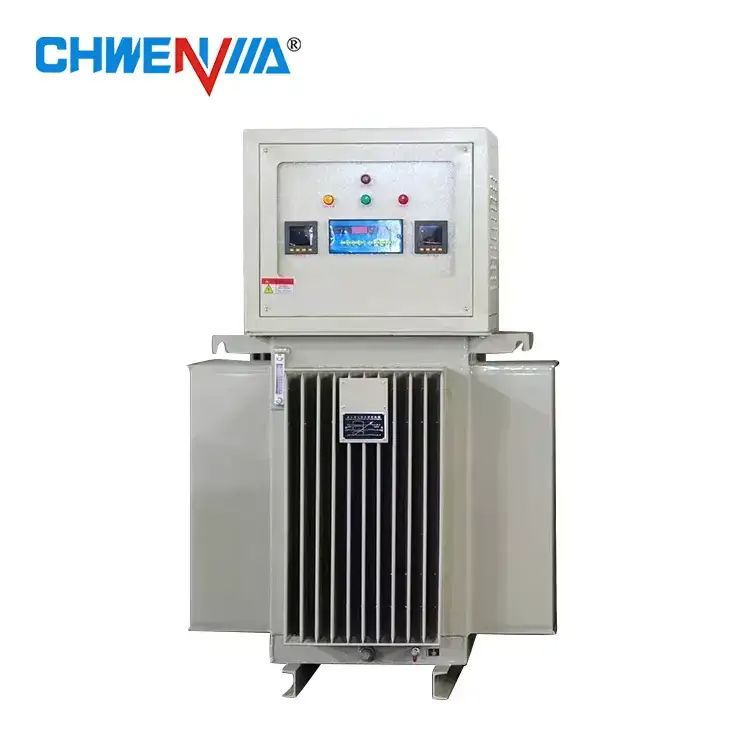
Thermal stability doesn't start in the oven; it starts at the winder. We keep conductor tension within a measured range instead of trusting the operator's hand. Uneven tension makes some turns stretch tighter than others, and those tighter turns expand at a different rate once the winding reaches operating temperature. We also avoid crossing conductors in the slot exit areas. Those crossovers might look tidy, but they concentrate mechanical stress and create a weak point that repeated heating will eventually crack.
Before any resin gets near the winding, the assembly is preheated long enough to drive out moisture from the insulation papers and slot liners. If that step is rushed, trapped water turns to steam during the bake and leaves voids behind. For the impregnation itself, we pull a deep vacuum and hold it past the point where bubbling stops, then flood the tank with varnish under positive pressure. This is slower than a simple dip-and-drain, but it forces resin into the small gaps near the end windings where thermal expansion is most aggressive.
The cure schedule matters just as much as the vacuum. We step the temperature up in stages rather than throwing the parts into a hot oven. A fast skin cure seals the surface and traps solvent inside, which weakens the bond at higher temperatures. After the full cure, we thermally cycle sample windings at low voltage to watch for micro-cracks or delamination before the batch is accepted. It adds a few hours, but it catches the kind of failure that shows up later in the field.
Why We Test Voltage Recovery With Motor Startups, Not Just Steady State
Most voltage checks look fine once a system settles into its running rhythm, but the moment a motor kicks on, the electrical picture changes entirely. Startup draws several times the normal current for a fraction of a second, pulling the bus voltage down before regulation circuits can respond. If you only test steady state, you miss the depth and duration of that dip, along with how quickly the source recovers. That recovery curve matters because downstream electronics, contactors, and even the motor itself can misbehave or drop out during those few cycles.
A generator or transformer may hold voltage rock-steady under constant load, yet stumble when asked to supply locked-rotor current. The governor, exciter, and voltage regulator all have response delays, and their interaction during a startup event often reveals weaknesses that a static test cannot. We routinely see voltage recovery times that differ by 30 to 50 percent between units that look identical on paper. Without loading the system dynamically, you cannot tell whether the controls are tuned to catch a falling voltage or merely to maintain one already stable.
The practical payoff shows up in commissioning and troubleshooting. A site that passes a steady-state test may still suffer nuisance trips, PLC reboots, or flickering lighting every time a compressor or pump cycles on. By focusing on motor startup, we catch the real-world stress that determines whether a power system is dependable under changing loads, not just under ideal, unchanging conditions.
Custom Tap Ranges and Phase Configurations for Unusual Mains
When the incoming supply doesn't match the standard three-phase or single-phase expectations, off-the-shelf transformers fall short. Unusual mains can present voltages well outside typical bands, frequencies that drift under load, or even non-standard phase counts like two-phase five-wire systems left over from legacy installations. For these situations, custom tap ranges and phase configurations aren't just an option—they're the only practical way to keep downstream equipment operating within safe limits.
A wide tap range on the primary winding lets a single unit accept, say, 380V up to 480V without swapping hardware, while a tapped secondary can be adjusted to deliver exactly the voltage your load demands. Phase configurations get more interesting: a Scott connection converts three-phase to two-phase for old industrial motors, while a zigzag grounding transformer creates a neutral point on an otherwise ungrounded delta system. In some plants, you'll find six-phase rectifier duty where a custom phase shift of 30 degrees between two bridges cancels harmonics far better than any passive filter.
The real challenge lies in making these custom solutions reliable. Thermal calculations must account for the worst-case tap under continuous full load, insulation needs extra margin when the supply voltage has high harmonic content, and the protection scheme has to recognize faults on any possible tap combination. Before shipping, every such transformer should undergo a full applied-voltage test and a phase-angle verification under simulated line conditions—because guessing wrong on an unusual mains supply can take down an entire process line.
Field Reports From Textile Mills and Injection Molding Lines
The weekly walkthrough started at a spinning mill outside Greenville. Three frames were down for roller bearing replacements, and the morning shift was still chasing a tension drift on ring frame six. I counted at least nine compressed air leaks loud enough to hear over the carding machines. The maintenance log showed the same leaks had been flagged twice in the past month, but the work orders kept getting bumped by unplanned doffing motor failures.
Over at the injection molding plant, a 350-ton press running glass-filled nylon was cycling 4.2 seconds slower than the process sheet allowed. The technician had raised the nozzle temperature to reduce short shots, but that only widened the gate freeze window and pushed flash onto two cavities. Scrap from the overnight shift filled three gaylords near the grinder. Nobody had checked the dryer dew point since Monday.
The pattern across both sites was not a lack of technical skill. Operators on both floors could describe exactly what was drifting out of tolerance. The missing piece was a clear handoff between shifts and a simple way to flag recurring issues without blaming the previous crew. That, more than any machine problem, is what keeps showing up in these reports.
What a 10-Year Warranty Actually Covers on Regulator Coils
Most people assume a decade-long warranty means any failure gets a free replacement, but the fine print on regulator coils usually narrows that down fast. The coverage typically applies to the coil's internal copper winding and the insulation around it. If the winding shorts out or the insulation breaks down under normal operating voltage and temperature, that's generally considered a valid claim.
What's not included often matters more. Physical damage from installation, corrosion from moisture or chemicals, and failures caused by voltage spikes from the vehicle's charging system are commonly excluded. Some manufacturers also require proof that the coil was installed with the recommended regulator and not exposed to prolonged overheating.
So that 10-year warranty is really a promise about manufacturing defects in the coil itself, not a blanket guarantee against every possible failure. Before buying, it's worth checking whether the warranty covers just the part or also the labor to replace it, since many only ship a new coil and leave the labor cost to you.
FAQ
Oil immersion provides much better heat dissipation, which keeps internal components cooler under continuous high loads. That directly reduces insulation stress and allows the unit to run at full capacity without derating, something dry-type designs struggle with in dusty or humid environments.
Every order starts with the client's actual grid data and load profile. Our engineers then select the appropriate core size, winding configuration, and control logic. We routinely build units with input ranges as wide as ±30% and output accuracy within ±1%, whether it's a three-phase 400V system or a single-phase 220V supply.
We see strong demand from plastic injection molding, CNC machining, medical imaging, textile mills, and cold storage facilities. These operations cannot tolerate voltage sags or phase imbalance because even brief fluctuations cause scrap, equipment faults, or data loss.
Each unit passes a full-load heat run for at least 48 hours, insulation resistance measurement, high-voltage withstand test, and response time verification under simulated grid swings. The test report with actual measured values ships with the unit so clients can verify performance independently.
Yes. The control circuit samples voltage continuously and corrects deviations within milliseconds without mechanical hunting. Built-in over-voltage, under-voltage, phase-loss, and surge protection automatically disconnect or bypass the load if conditions fall outside safe limits.
We provide remote commissioning guidance through video calls, a full set of English manuals and wiring diagrams, and a two-year warranty on the complete unit. Spare parts like control boards and cooling oil remain available for at least ten years after the model is discontinued.
The oil not only cools but also seals out moisture and oxygen from the windings, which slows corrosion and insulation aging. Maintenance mostly involves periodic oil sampling and checking for leaks. With proper care, these stabilizers commonly last 15 to 20 years in continuous operation.
Conclusion
A top oil immersed voltage stabilizer factory in China proves itself in delivering superior power quality under load, not on a polished datasheet. Inside the tank, the oil and core work together to absorb heat while the regulator corrects incoming voltage, which matters most when a textile loom or injection molding machine starts abruptly. We wind and vacuum-impregnate every coil without shortcuts because poor impregnation shows up later as insulation hot spots or partial discharge. Voltage recovery tests run with real motor startups—locked-rotor current for a few cycles—rather than steady-state resistive loads. If the stabilizer cannot pull voltage back quickly, the line drops out. That is the standard we hold.
Unusual mains are handled with custom tap ranges and phase configurations instead of forcing a site into a one-size-fits-all unit. Textile mills and injection molding lines often have severe phase imbalance or long cable runs, so a stabilizer has to tolerate swings of fifteen percent or more. Field reports from those plants repeat the same demand: stable output during rapid load changes, including generator changeover. The 10-year warranty on regulator coils reflects this. It covers the copper winding, insulation, and tap changer contacts under normal operating cycles—not just the outer enclosure or control panel. When coils are built for repeated inrush events, a long warranty is not marketing; it is a maintenance calculation.
Contact Us
Contact Person: Mr. Jiang
Email: [email protected]
Tel/WhatsApp: +86-15057775503
Website: https://www.avrfactory.com/