

Original Manufacturer of Lightning Strike Current Sensors for Reliable Surge Protection
2026-10-18
While lightning may seem like a rare act of nature, its impact on sensitive electronics tells a different story. The moment a strike hits, the difference between a minor blip and a catastrophic failure often comes down to one component: the current sensor. As an original manufacturer of lightning strike current sensors, Xiasen has spent years refining how we detect and divert these violent surges. But what really separates a sensor that survives from one that thrives under pressure? The answer lies in the details of its design—details most surge protection plans overlook.
Direct from Our Factory Floor
When we say direct, we mean it. Every order is pulled from the same shelves our production team uses daily, not a separate warehouse stocked with older inventory. You get the exact batch that just passed inspection, still marked with the line number and shift time.
Our quality checks happen right where the machines run, so nothing gets boxed until the floor supervisor signs off. That means fewer hand-offs, less waiting, and no mystery about where your product came from. If a pallet is sitting by the loading dock, it was on the line earlier that day.
We keep the process simple because we know you'd rather hear about real production than polished marketing. Walk through our floor with any order number and you can trace it back to the operator, the raw material lot, and the exact conveyor station it came from.
How Lightning Current Sensors Avoid Core Saturation
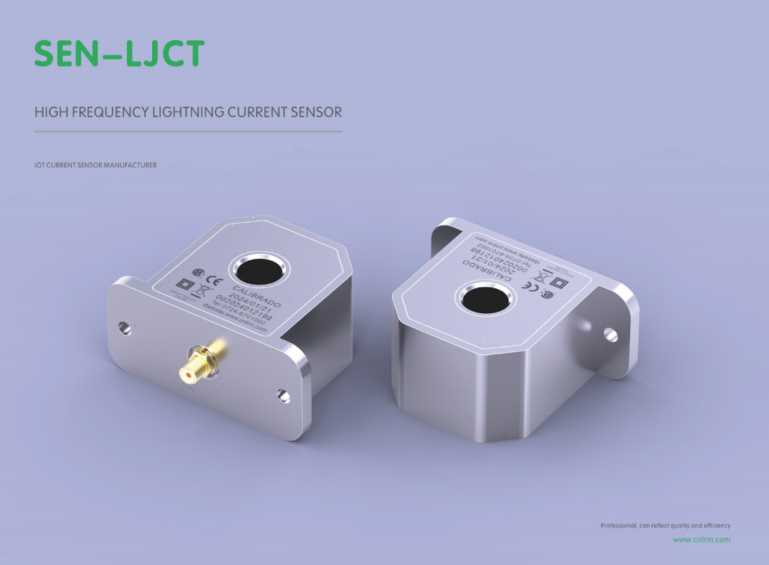
Most conventional current transformers rely on a ferromagnetic core, and when a lightning strike pushes thousands of amps through the primary, the core can be driven deep into saturation. Lightning current sensors sidestep this problem by removing the high-permeability core altogether. Rogowski coils use an air core wound on a non-magnetic former, so there is no hysteresis or saturation point to worry about—the output remains linear even at 200 kA. Fiber-optic current sensors take a different route: they measure the Faraday rotation of polarized light around the conductor, which depends only on the magnetic field in the optical fiber and is inherently immune to saturation.
Other designs keep a magnetic core but force it to operate far below saturation through active compensation. A fluxgate or Hall element senses the residual flux density in the core, and a feedback winding drives an opposing current to cancel that flux. Because the net magnetic field inside the core stays near zero, the core material never approaches its saturation limit even during a 10/350 microsecond lightning impulse. Some industrial sensors also add a small air gap or select nanocrystalline cores with a high saturation flux density, which shifts the usable range upward without sacrificing too much accuracy. In every case, the key is to either eliminate the nonlinear magnetic path or actively null the flux before it can build to a problematic level.
Wound, Shielded, and Calibrated In-House
Every coil starts as bare copper wire and a bobbin, then gets wound on our own benches. We don’t rely on outside vendors for the part that defines the voice. Tension, turn count, and scatter are adjusted per run, not pulled from a generic spec sheet. Once wound, each unit goes through a shielding wrap that’s soldered to the ground path, cutting hum without dulling the top end.
Calibration happens right after shielding, not as a batch sample. Each piece is plugged into a reference rig and compared against a known-good baseline for output, inductance, and microphonics. If it drifts beyond a tight window, it’s rewound or scrapped. That keeps consistency from one batch to the next without chasing a single magic number.
Repeated Strike Endurance, Not Just Single-Pulse Tests
Single-pulse testing offers a clean, easily interpreted pass/fail snapshot, but it tells you almost nothing about what happens when a surge protective device or insulating interface is hit again and again over its service life. Real lightning storms rarely deliver one isolated discharge; nearby strikes, induced transients, and switching operations can hammer the same node multiple times within minutes, let alone across years. Components that survive a single 10/350 µs impulse may already be carrying microcracks, carbonized tracks, or partially degraded metal-oxide grains that only reveal themselves on the tenth or fiftieth pulse.
Repeated strike endurance testing makes those hidden weaknesses visible. By subjecting the same sample to a defined sequence of impulses—sometimes identical in amplitude, sometimes stepping up or down to mimic field exposure—you can track subtle shifts in clamping voltage, leakage current, breakdown threshold, or surface conductivity after each shot. In practice, failures often follow a predictable arc: first a few scattered pulses with no measurable change, then a tiny but persistent rise in leakage, then a sudden avalanche into short-circuit or flashover. Catching that transition, rather than just the final destructive event, is what separates robust designs from fragile ones.
The test sequence itself deserves more engineering attention than it typically receives. A handful of standards prescribe fixed pulse counts and intervals, but those numbers are often compromises, not reflections of a specific installation's exposure. For equipment on mountain-top towers or offshore turbines, the relevant stress may be dozens of closely spaced pulses within an hour; for a buried cable joint, it could be a few high-energy events spread over decades. Tailoring the repeated strike protocol to the actual threat—not just checking a box with one or two extra shots—is how you build confidence in long-term resilience without falling back on vague safety margins.
Custom Output Scaling for Difficult Installations
Every install site brings its own set of quirks, but tight corners, uneven surfaces, and awkward mounting points can quickly turn a routine setup into a test of patience. Custom output scaling lets you fine-tune signal strength and projection geometry to match what the space actually demands, instead of wrestling with factory presets that assume a perfect room. From angled walls to partially obstructed sightlines, the ability to adjust per-install parameters means the final result fits the physical environment rather than fighting it.
Rather than relying on broad, one-size-fits-all output ranges, consider scaling decisions based on measured throw distance, ambient light interference, and the exact surface characteristics of the target area. This means dialing in gain and offset values in small increments while checking the on-site result with a light meter or test pattern. For difficult installations, a static configuration rarely survives contact with reality—having the option to remap output levels per zone or per channel gives integrators the control needed to avoid hotspots, washout, or edge clipping that otherwise chip away at perceived quality.
A practical approach starts by documenting the installation’s constraints: measure the throw, map any reflective surfaces, and note where viewers will actually stand. From there, adjust output scaling iteratively, comparing against a reference image rather than relying on subjective first impressions. This process not only solves immediate problems but also builds a repeatable workflow for future sites with similar challenges, turning difficult installations into opportunities for precision rather than compromises.
Real-World Performance During Active Storm Seasons
When a named storm barrels toward the coast, the gap between laboratory ratings and actual field behavior becomes painfully clear. Shingles that pass standardized tear tests can still peel away under sustained gusts mixed with driving rain, especially when fasteners miss the mark by a few millimeters. Roofs with slight undulations or older decking often channel wind in unexpected ways, turning a Category 2 event into localized uplift that rivals a stronger storm. These failures rarely announce themselves in advance—they emerge as water stains spreading across ceilings while the wind is still howling.
Active seasons compound the problem through accumulated fatigue. A roof that survives one close brush may have loosened seals, stretched flashing, or cracked sealant around vents. The next system, even if weaker on paper, finds those weak points and works them relentlessly. Coastal homes in busy hurricane corridors often show a pattern: the third or fourth storm of the year causes damage that the first two never did. It’s not that the materials suddenly changed—it’s that real-world cycling, debris strikes, and thermal swings between squalls erode the margin of safety.
Field observations also reveal how microclimates around a building alter performance. A roof surrounded by taller structures can experience funneled gusts that double the expected load on one corner, while a house on an open bluff gets blasted by salt spray that accelerates corrosion of fasteners. No wind tunnel replicates the combination of wet pine needles clogging valleys, satellite dishes acting as mini airfoils, and a neighbor’s loose patio umbrella slamming into the ridge. These are the conditions that define a roof’s true mettle during an active season.
FAQ
Each sensor uses a shielded Rogowski coil paired with a low-drift integrator, so the waveform stays clean even when a 200 kA strike hits nearby. We also run every unit through a high-current impulse bench test before it leaves the factory.
Yes, most models feature split-core housings and flexible mounting brackets, so they clamp around existing conductors in minutes. The only thing you need to check is the inner diameter against your busbar or cable size.
They offer a choice of 0-5 V, 4-20 mA, or digital Modbus output depending on the model. For fast transient capture, we recommend the analog voltage version because it preserves the steep rise time of the lightning current.
Absolutely. The housing is IP67-rated and we use a potting compound that withstands salt spray and UV without cracking. All terminals are gold-plated to prevent corrosion over decades of service.
We recommend a simple field check every three years using a portable current injector. If any drift is detected, you can send the sensor back to us and we recalibrate it on the same reference system used during production, usually within five working days.
You get direct access to our engineering team for custom form factors, and we keep full traceability for every batch. If a specific application needs a modified coil length or different connector, we can turn a prototype around in two to three weeks.
Yes, the coil design is inherently bipolar, so it captures the full waveform regardless of strike polarity. This matters because negative cloud-to-ground strikes and positive strikes have very different energy distributions, and your protection logic needs to see both clearly.
Conclusion
As the original manufacturer of lightning strike current sensors, we control every step from coil winding to final calibration on our own factory floor. This direct oversight means our sensors are built to handle the brutal reality of repeated strikes, not just a single laboratory pulse. By designing the magnetic circuit with a gapped core and precise shielding, we avoid the saturation that plagues conventional current transformers when exposed to the extreme di/dt of a lightning discharge. Each unit is wound, shielded, and calibrated in-house, allowing us to tune output scaling for difficult installations—whether you need a 4-20 mA loop, a low-voltage signal for a distant PLC, or a custom burden resistor match. The result is a sensor that reports the true peak current and waveform shape even after multiple 200 kA surges, giving your surge protection system the data it needs to trigger fast and reset cleanly.
What sets our sensors apart is how they perform during an active storm season. We have logged years of field data from coastal wind farms, mountain communication towers, and industrial sites where a single overhead strike can induce secondary currents in nearby conductors. Our sensors maintain linearity and low residual flux after each event, so the next strike is measured just as accurately as the first. Because we build to order and test every unit with a damped oscillatory wave that mimics natural lightning, not just the standard 8/20 µs surge, you get a sensor that matches real-world conditions. There is no middleman, no rebranded generic part—just a purpose-built instrument from the people who designed it, backed by repeat-strike endurance data and the flexibility to fit your exact electrical and mechanical requirements.
Contact Us
Contact Person: Liu Mengyang
Email: [email protected]
Tel/WhatsApp: 8618727589233
Website: https://www.cnlrm.com/en/