

High Quality Motorized Regulating Valves: A Practical Guide to Precision Flow Control
2026-11-23
Most flow control problems don’t start with the valve you can see—they start with the one nobody thought twice about. In process lines, HVAC loops, and industrial fluid systems, a motorized regulating valve does far more than open and close; it sets the rhythm for stable pressure, repeatable temperature, and predictable energy use. This guide cuts through datasheet noise to focus on what precision actually demands: control accuracy, material compatibility, response time, and long-term reliability. We’ll also look at how HONGSEN designs motorized regulating valves for tighter control without adding unnecessary complexity.
What Precision Flow Control Actually Demands from a Motorized Valve
Precision flow control isn't about how finely a valve can be stepped in a catalog. It's about repeatability when the system has thermal drift, when line pressure shifts by a few percent, or when the media's viscosity changes after a cold start. A motorized valve that performs well on a test bench often falls apart in these real conditions because its internal deadband, backlash, and seat friction add up to a positional uncertainty that no control loop can fully correct. What actually matters is how the valve responds to small command changes under load, not the nominal resolution printed on a datasheet.
The motor itself is rarely the limiting factor. The mechanical connection between the actuator and the trim is where most of the precision is lost. Unless the valve is designed with near-zero lost motion between the motor shaft and the seat, the first few percent of travel after a direction reversal may produce no change in flow at all. This forces the controller to hunt, overshoot, or add dithering that wears out seals prematurely. A well-engineered motorized valve hides this behavior by using a preloaded drive train or a direct-coupled stem so that every encoder count corresponds to something happening at the orifice.
Temperature stability is another demand that gets overlooked. The actuator housing heats up during operation, and if the feedback element isn't thermally compensated, the reported position drifts even when the physical opening hasn't moved. For flow control loops that run continuously for hours, this drift can be mistaken for a process disturbance, triggering unnecessary corrections. The best designs treat the valve as a system: the motor, gear reduction, position sensing, and seat geometry all have to remain coherent across the operating envelope, not just at ambient calibration conditions.
Why Two Identical Valves Can Deliver Completely Different Flow
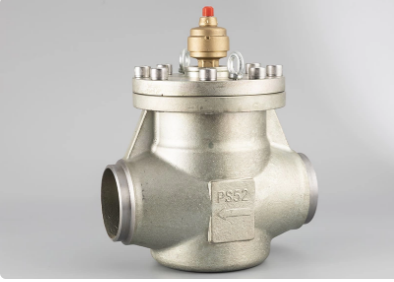
Identical on paper rarely means identical at the flow path. Two valves from the same production line can have subtle differences in seat concentricity, plug contour, spring preload, and internal clearances. These small deviations change the effective throttling area and the local pressure recovery, so at the same nominal opening and differential pressure, one valve may pass noticeably more fluid than the other. Even when the model number and trim designation match, accumulated manufacturing tolerances can shift the installed flow coefficient enough to produce a measurable split between parallel branches.
Installation and calibration often separate two otherwise equal valves. Pipe misalignment can impose lateral loads on the stem and guide, altering how smoothly the plug moves and where it actually seats. If actuator travel is not calibrated for each valve individually, the same control signal can produce different actual plug positions. Inlet straight-run length, gasket protrusion, or a slightly different orientation of the seat ring after assembly can disturb the entering flow profile, changing the effective capacity in ways that are not visible from the outside.
Once in service, the two valves begin to accumulate different histories. Erosion, cavitation pitting, seal deformation, or deposits on the seating surfaces may develop unevenly even under similar process conditions. A valve that has experienced mild cavitation on the seat edge will have a different discharge characteristic than a valve with an undamaged seat, despite both still being classified as the same product. For this reason, assuming equal flow from identical valves can lead to misleading balancing decisions; only individual flow verification can reveal what each valve actually delivers.
Matching the Valve Trim to the Loop Instead of the Line Size
A valve sized to match the pipe often ends up over-sized for the actual control task. The line size reflects full-flow capacity, but most loops operate well below that for long stretches. When the trim is chosen this way, small increments in signal produce disproportionately large changes in flow, which forces the positioner to hunt and wears out the seating surfaces early.
It helps to look at the loop's normal operating band instead of the pipe diameter. Consider the minimum, typical, and upset flow rates, then pick a trim that places those conditions in the controllable portion of the valve's range. This usually means accepting a smaller valve body with reducers rather than forcing an oversized trim into an existing line. The minor extra piping cost is often recovered quickly through more stable control and less maintenance.
The loop also dictates what kind of characteristic makes sense. If the pressure drop shifts with load, an equal-percentage trim can compensate for the process nonlinearity, whereas a linear trim may work when the valve handles most of the system pressure drop. These choices only become clear when the control requirements drive the selection, not the convenience of matching flanges.
The Calibration Step That Separates Stable Flow from Constant Hunting
Most calibration routines fail quietly not because the math is wrong, but because the reference points are too far from the conditions that actually matter. A bench-level calibration at room temperature can pass every time while the sensor still misreads at operating temperature or under load. The step that changes the outcome is mapping the instrument's response across the range where it has to hold steady, then storing that curve instead of relying on a single zero and span.
What separates stable flow from constant hunting is whether adjustments come from a verified offset or from a guess. When the baseline has real checkpoints, a small drift becomes a known correction that gets applied consistently. Without that, the same drift looks like the process moving, so operators end up trimming gains, moving setpoints, and chasing readings that never settle. Calibration puts the error back on the measurement side, where it belongs, instead of letting it leak into every control decision.
How Electrical Noise Turns a Precise Valve into a Drifting One
A perfectly tuned proportional valve can hold a flow rate within a fraction of a percent on the test bench, yet the same unit installed near a variable frequency drive may wander by several percent without any change in command signal. The reason is rarely mechanical wear. Electrical noise, whether radiated from nearby power cables or conducted through shared ground paths, sneaks into the valve's control loop and masquerades as a legitimate setpoint change. Once that noise reaches the amplifier or the feedback transducer, the valve begins to shift in ways that look like drift but are actually rapid, small corrections driven by interference.
The mechanism is often subtle because the noise is not strong enough to cause an obvious fault. A few millivolts of common-mode ripple on a 4–20 mA loop can be interpreted by the valve controller as a tiny pressure or position error. The onboard electronics then try to correct that false error, nudging the spool slightly. Over minutes or hours, these micro-corrections accumulate, and the process variable creeps away from the intended operating point. Operators notice the drift and assume the valve needs recalibration, when in reality the closed-loop control is fighting an invisible electrical disturbance.
Shielded cables, proper grounding, and separation of signal wiring from power wiring can eliminate most of this behavior, but only if the noise path is correctly identified. A quick test is to observe the valve command signal with an oscilloscope while the machine runs normally. If the trace shows a fuzzy or stepping pattern instead of a clean flat line, the valve is not drifting on its own, it is being pushed around by the electrical environment. Fix the interference, and the precise valve returns to its precise behavior.
A 20-Minute Field Routine for Verifying Regulating Accuracy
A quick field check doesn't require a lab full of instruments. Start by letting the regulator breathe against a dead-ended downstream valve, then crack a small bleed downstream and watch how the delivery pressure settles. Compare that settled reading with the tag value, then repeat at a different flow point using a portable orifice or a hand valve cracked just enough to create a slight draw. The key is to observe recovery time and the width of the swing, not just the final number.
Many technicians skip the ambient temperature step. Regulator springs and diaphragm stacks shift with heat, so before you judge accuracy, let the unit sit in the pipe environment for ten to fifteen minutes. Then run the same two-point check: one near lockup, one mid-range. If the mid-range reading drifts more than a few percent while the lockup stays tight, suspect a worn seat or a diaphragm that has taken a set.
Finally, record the results in a simple three-column note: setpoint, observed pressure, and recovery seconds. That log becomes more useful than a pass/fail tag because it shows trends. A regulator that creeps toward the setpoint over eight seconds today may still meet spec, but against next month's notes you can catch a developing friction problem before it becomes an upset downstream.
FAQ
It comes down to positioning accuracy, repeatability, and how the valve behaves under partial load. A regulating valve is designed to hold intermediate positions with minimal hysteresis, whereas a standard motorized ball valve often works best as an open/close device. Materials, stem sealing, and the actuator's deadband also matter more than most people expect.
If the rest of the system already uses a PLC with analog outputs and you want straightforward wiring, 4-20 mA is still difficult to beat. Digital buses make more sense when you need diagnostics, several valves on one trunk, or the ability to change settings remotely without opening the actuator cover.
Cv only tells you the fully open capacity. What matters at low flow is the valve's inherent characteristic and how well the actuator can resolve small steps. Equal percentage trim, proper sizing, and a motor with fine step resolution usually deliver much smoother control than an oversized valve with linear trim.
It is usually a combination of an oversized valve, aggressive PID tuning, or too much deadband in the actuator. Sometimes the feedback signal is noisy because the position transmitter is poorly mounted or the signal wiring shares a conduit with variable frequency drive cables.
Most high-quality units can be oriented in any position, but the actuator weight and possible condensate drainage should be considered. For steam or very wet service, horizontal mounting with the actuator above the body can help keep the motor and electronics dry, and it often improves maintenance access.
Inspect stem packing for leaks, verify that the feedback signal matches the physical position, listen for gear wear or grinding, and keep the actuator enclosure sealed against moisture. Checking zero and span once a year catches calibration drift before it turns into a process problem.
It deserves more attention than the brand name. An equal percentage characteristic often matches heat exchanger and pressure control loops better than linear trim, especially when the valve was originally oversized or the load varies widely. Matching the new trim to the actual operating range avoids a repeat retrofit in a year or two.
Conclusion
Precision flow control with a motorized regulating valve is less about catalog specifications and more about how the assembly behaves under real loop conditions. Two valves with the same size and Cv can deliver completely different flow because trim geometry, seat wear, packing friction, and actuator deadband all shift the relationship between command signal and actual movement. The practical takeaway is that selection should start from the control loop's required turndown and sensitivity rather than simply matching line size. A smaller trim with higher resolution often outperforms an oversized body running near the seat, where tiny position changes create exaggerated flow swings. Bench performance may look smooth, but the installed characteristic bends once piping geometry, pressure drops, and process noise enter the picture.
Stable regulation depends on a deliberate calibration sequence rather than a single setting. Stroking the valve through its full range, confirming the positioner tracks real stem movement, and tuning feedback gain so the valve settles without hunting are all part of that routine. Electrical noise from VFD cables, ungrounded shields, or poor 4–20 mA loops can masquerade as valve drift, so signal integrity checks belong in the field. A short 20-minute verification covering commanded versus actual position, steady-state repeatability, and response to a small setpoint bump reveals whether the valve is truly regulating or only moving. Teams that treat these checks as routine catch trim erosion, air supply issues, and noise problems before they turn into process variability.
Contact Us
Contact Person: KOPASS HO
Email: [email protected]
Tel/WhatsApp: 8613606566112
Website: https://www.hongsenref.com/