

Custom Sampling Valve Solutions for Safe and Accurate Process Sampling
2026-09-13
Accurate process sampling often gets treated like a routine checkbox until a faulty valve contaminates a batch or puts an operator at risk. Standard sampling valves rarely fit the unique demands of corrosive media, extreme temperatures, or tight purity specs. That’s where AVM takes a different route, custom engineering sampling solutions around your actual process rather than a catalog page. Because when safety and sample integrity are non-negotiable, close enough simply isn’t an option. Read on to see how tailored valve design changes the game.
Why a Standard Valve Geometry Rarely Fits Your Sampling Point
Sampling points in process lines are rarely located in straight, unobstructed pipe runs with fully developed flow. Standard valve geometries assume a clean bore and a uniform velocity profile, but real installations often sit just downstream of elbows, reducers, or partially open block valves. That mismatch means the valve’s internal contours—designed for ideal bench conditions—can create dead zones or turbulence right where you need a representative grab sample.
The threaded or flanged connection geometry also plays a role. Standard valve bodies have a fixed insertion depth and port orientation, which may leave the sampling nozzle recessed behind a pipe wall or protruding into a stagnant boundary layer. Field modifications like weld-on nipples or extended reach probes are frequently required, because a generic valve cannot account for insulation thickness, pipe schedule variations, or the thermal expansion offsets that accumulate at real sampling points.
Containment-First Sealing: Double Block-and-Bleed Done Right
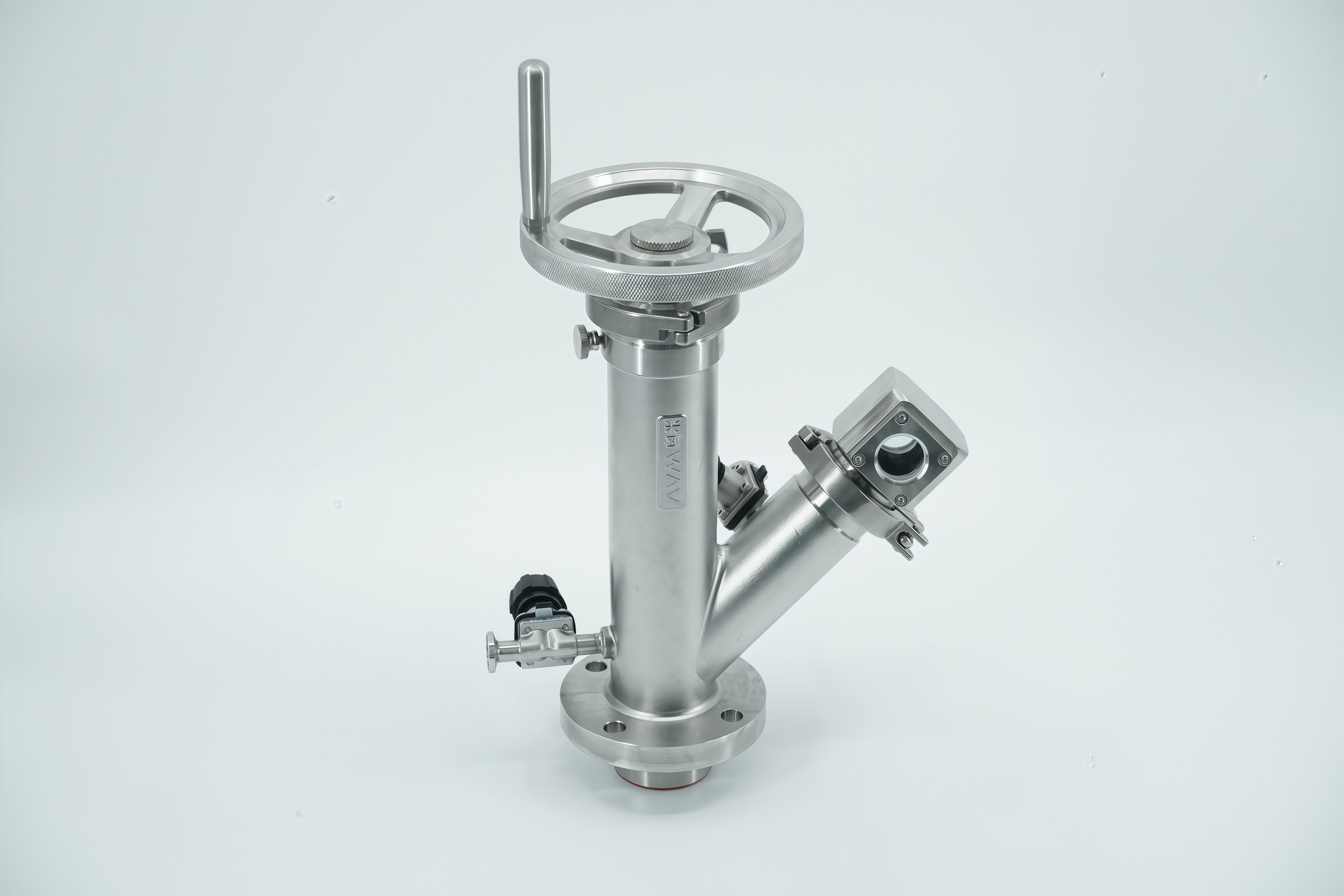
Containment-first sealing isn't about adding more seals; it's about ordering the sealing sequence so the primary barrier is fully isolated before any maintenance path opens. In double block-and-bleed (DBB) setups, that means both upstream and downstream isolation valves close tight and hold pressure independently, and only then does the bleed port get opened to verify zero leakage across the seat.
A proper DBB arrangement relies on two distinct seating surfaces per isolation valve, not just a single wedge gate that can trap pressure between seats. The bleed between them acts as a witness point: if the upstream seat leaks, pressure appears at the bleed before it can reach the downstream side. This confirmation step is what separates a true containment-first design from a simple two-valve block that leaves hidden cavities unproven.
In practice, operators who adopt this philosophy avoid the common mistake of opening the bleed while the line is still pressurized against a single closed valve. Instead, they close the upstream isolation first, confirm the downstream isolation is seated, then crack the bleed to atmosphere or a safe vent. Only after pressure decays to zero do they proceed with breaking flanges or removing spools. That sequence protects both the worker and the process from unexpected inventory release.
Chasing Dead Space Out of Every Wetted Corner
Most damp problems in bathrooms and laundry rooms don't start on open surfaces. They begin in the narrow gaps behind a sink pedestal, under the lip of a bathtub, inside an overflow channel, or where the floor meets a cabinet toe-kick. These are the wetted corners that never fully dry. A quick wipe of the visible tile leaves them untouched, so the same musty odor returns within days. Chasing dead space means treating these hidden recesses as part of the cleaning zone, not as afterthoughts.
Start by mapping where water actually travels. Use a thin nozzle or angled brush to reach the seam between the tub and wall, the underside of the faucet base, and the groove around the drain collar. After rinsing, do not rely on air drying alone. Pull moisture out with a microfiber cloth, a wet-dry vacuum, or a targeted stream of compressed air. The goal is to leave no pocket where a damp film can survive. If a joint or caulk line stays dark or soft, it is still holding water and needs attention.
When the hidden areas stay dry, the whole room behaves differently. Odors fade, grout stops darkening at the edges, and painted surfaces don't peel as quickly. It turns cleaning into a practice of eliminating moisture traps rather than just polishing what is already easy to reach. That shift is what finally pushes dead space out of every wetted corner.
Alloy and Liner Choices for Sour, Caustic, or Slurry Streams
Selecting the right material for piping that carries sour, caustic, or slurry media often means balancing two competing demands: resisting chemical attack and enduring mechanical wear. Sour streams, with their dissolved hydrogen sulfide, can trigger sulfide stress cracking in standard carbon steel, so leaner alloys with controlled hardness or a nickel-based cladding become necessary. Caustic service, especially at elevated temperatures, invites caustic embrittlement if the steel isn't stress-relieved, while higher concentrations may require austenitic stainless steels or nickel alloys to avoid rapid thinning. Slurry lines, on the other hand, face abrasive erosion from suspended solids, so a hard internal liner—such as a ceramic, basalt, or a weld overlay of chromium carbide—often outlasts even a corrosion-resistant bare alloy.
A practical approach is to map the dominant failure mode before finalizing the alloy and liner combination. If chemical attack is the primary concern, a corrosion-resistant alloy like duplex stainless steel or Alloy 20 can handle many sour and caustic scenarios, but the wall thickness should still account for some erosion allowance. When abrasive wear drives the failure, a dual-layer system works well: an outer carbon steel shell for structural strength and a replaceable internal liner made of polyurethane, rubber, or hardened metal. For mixed sour and slurry conditions, consider a corrosion-resistant backing alloy lined with a chemically inert ceramic, though this adds fabrication complexity and cost. Field experience shows that the cheapest upfront material rarely wins; downtime from a liner failure or a stress crack in a sour line can erase years of savings.
One often-overlooked factor is the synergy between pH swings and particulate loading. A caustic slurry, for instance, can accelerate erosion-corrosion at elbows and reducers, where the protective oxide film is continually stripped away. Here, a higher-alloy base with a hardened internal surface—such as a tungsten carbide overlay on a stainless steel pipe—may provide a longer service interval than either material alone. Similarly, sour gas pipelines that occasionally carry produced sand benefit from a bimetallic pipe with a corrosion-resistant alloy inner layer and a wear-resistant outer layer, though the liner's weldability and inspection access must be verified during design. Ultimately, the right choice depends not on a generic specification but on the actual temperature, velocity, solids concentration, and H₂S partial pressure seen in operation.
Rebuilding In Place: Cartridge Seals and Top-Entry Access
A cartridge seal is delivered with the rotary face, stationary face, springs, and shaft sleeve already fitted into a single gland assembly. That changes field service: instead of measuring and setting face load against a shoulder, the mechanic only removes the old gland bolts, slides the worn cartridge off the shaft, and slides the replacement on. The impeller stays where it is, so clearances and coupling alignment aren't touched.
Top-entry access puts the seal housing on the upper end of the machine. On vertical pumps and top-entry mixers, this opens a direct line to the stuffing box without lifting the motor, gearbox, or entire shaft assembly. The technician works from above—often from a catwalk or ladder—and can reach all gland fasteners, flush ports, and the cartridge clamp ring without breaking the process connection below.
The practical result is an in-place rebuild that fits a normal maintenance window. The casing remains bolted to the pipe or vessel, the shaft stays in its bearings, and the seal is renewed as one cartridge. Worn O-rings, drive pins, and faces go back with the old part; no lapping, no spring compression jig, and no realignment afterward.
From Handwheel to Fully Automated: Actuation Without New Piping
Many existing valves were installed with only a handwheel, yet upgrading them to automated control rarely demands cutting into the line. A direct-mount actuator fits over the valve's existing stem or handwheel shaft using a machined drive sleeve and a simple bracket, so the body stays in place. The original piping remains untouched, which removes the need for new welds, flanges, or pressure tests tied to pipe modification.
This approach works because the torque interface is already there. The handwheel's square or keyed stem can be matched to an electric or pneumatic actuator with a dimensioned insert, while the valve's ISO or custom mounting pad supplies a rigid anchor point. Once the actuator is bolted on, the handwheel can be left as a manual override or removed entirely. The result is full open-close or modulating control without draining the line or isolating the process longer than a routine maintenance window.
Plants with legacy manual valves gain a practical path to automation. Gate, globe, ball, and butterfly valves are common candidates, especially where space is tight or the pipe rack is congested. Because no new piping is added, the original flow characteristics and documented layout stay unchanged, yet the valve can now respond to a control system. This makes retrofits far less disruptive than replacing the whole valve assembly.
FAQ
A custom solution is built around your specific process conditions—things like line size, pressure, temperature, and the nature of the fluid. Instead of adapting a generic valve, the design starts with your actual operating parameters so the valve fits seamlessly into the system and performs reliably from day one.
They reduce direct exposure to hazardous media by incorporating features like spring-to-close handles, interlocking mechanisms, and dead-space-free construction. Because the valve is matched to your pressure and temperature envelope, there's less risk of unexpected leaks, spray-out, or accidental opening under process conditions.
Accuracy suffers when sample lines have dead legs, pockets, or areas where fluid can stagnate or mix with previous batches. A well-designed custom sampling valve keeps the sample pathway short and flush, so what you collect truly represents the current process stream rather than a contaminated or diluted leftover.
Chemical processing, pharmaceuticals, food and beverage, oil and gas, and water treatment are common. Any industry that handles aggressive, sterile, or high-purity media and must verify product quality or meet safety regulations can benefit from a tailored sampling valve rather than a one-size-fits-all unit.
You need to provide the line pressure, operating temperature, fluid composition, viscosity, particle content, and whether cleaning or sterilization is required. Also state the connection type, sample volume, and whether the valve must be locked or interlocked. The more precise these details, the better the final design matches your actual sampling task.
Yes, but the design differs significantly. Gas sampling often requires lower dead volume and special sealing to prevent leakage, while liquid sampling may need drain ports or cooling jackets for high-temperature fluids. A custom approach lets the valve be optimized for the phase, rather than using a compromise design that works poorly for both.
Material choice affects corrosion resistance, wear life, and product purity. For example, stainless steel works for many chemical applications, but aggressive acids may call for Hastelloy or PTFE-lined bodies. Matching the wetted materials to your exact fluid prevents premature failure and avoids contaminating the sample with metal ions or particles.
Because the valve is designed for your specific process, maintenance tasks like seal replacement or cleaning are often simpler. The design can include features such as quick-release clamps, minimal internal parts, or self-draining body geometry, which cuts downtime and makes routine service less error-prone.
Conclusion
Process sampling rarely rewards off-the-shelf thinking. A standard valve geometry often forces compromises at the tap point, leaving pockets of stagnant fluid that distort grab samples or create safety risks. Custom designs begin with the actual pipe profile and orientation, machining the body so the sample path stays short and fully swept. Containment-first sealing is not an afterthought; the double block-and-bleed arrangement is reworked around the specific seat layout, ensuring both barriers close tightly before the bleed opens. Every wetted corner gets scrutinized, with dead legs eliminated through angled ports and flush internals rather than simply accepting the nearest catalogue shape.
Materials follow the stream, not the stock list. Sour gas, hot caustic, and abrasive slurry demand distinct alloys or lining systems, often combined with hardened trim where erosion bites hardest. Maintenance thinking changes too: top-entry access and cartridge-style seals let a worn valve be rebuilt in place without cutting into the line. When the process moves toward automation, the same custom body can accept a pneumatic or electric actuator without reworking adjacent piping, preserving the original footprint while adding remote control. The result is a sampling point that reads true and stays contained over years of service, not just on day one.
Contact Us
Contact Person: Ananda
Email: [email protected]
Tel/WhatsApp: 8619016718200
Website: https://www.wzaomi.com