

Custom Motor Magnets: Tailored Magnetic Solutions for Your Application
2026-08-15
Your motor design deserves more than a one-size-fits-all magnet. Whether you're chasing higher efficiency, tighter space constraints, or a unique torque profile, custom motor magnets are the key to unlocking real performance gains. At DAWA, we specialize in tailored magnetic solutions that match your exact specifications—so your application runs smoother, cooler, and stronger. Ready to see what a custom magnet can do? Read on.
Magnet Geometry First, Motor Compromises Later
Most motor design workflows treat the magnet as a fill-in-the-blank part: pick a rough rotor diameter, choose slot/pole combination, wind the stator, then squeeze in whatever magnet fits. Reversing that order changes the conversation. When magnet geometry drives the design, you start with the flux waveform you actually want—sinusoidal or trapezoidal—and shape the magnet to produce it. That might mean a curved face, a segmented arc, variable thickness, or a Halbach arrangement. The stator and rotor iron then get adjusted around that magnet, not the other way around.
The payoff shows up in places like cogging torque and harmonic losses. A properly shaped magnet can suppress certain spatial harmonics without adding active control or skewing the stator, which would otherwise sacrifice torque. The compromise is that the motor around it has to give ground: rotor back iron may get thinner, air-gap length may increase slightly, or the magnet retention features need a more complex shape. Those are real costs, but they are usually cheaper than trying to fix a bad magnet shape later with more current or filtering.
This approach is not a universal rule. In cost-driven, high-volume designs, a simple rectangular magnet and a forgiving motor may still win. But for servo applications, robotics, or low-noise drives where torque quality matters more than saving a few machining steps, letting magnet geometry lead prevents a lot of downstream compromise. Once the magnet is right, the rest of the motor finds a way to work around it—and that is often the better trade.
Alloy Selection for Real-World Torque and Temperature
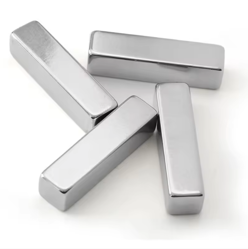
Selecting the right alloy for components that face both high torque and fluctuating temperatures demands more than a quick glance at a datasheet. Engineers often start with familiar names like 4140 or 4340, but real-world failures show that hardenability, tempering response, and hot hardness need to be weighed together. A part that survives a short lab test can crack weeks later when thermal cycling softens the core or reduces clamping force. The key is to map the actual load path and temperature envelope before narrowing down candidates.
For moderate heat with heavy mechanical stress, micro-alloyed steels and precipitation-hardening stainless grades can outperform traditional quenched-and-tempered alloys. The reason lies in their ability to retain strength without relying solely on martensite. In powertrain and tooling applications, an alloy like 17-4 PH or a vanadium-modified medium-carbon steel may hold dimensions better than a plain carbon grade, because it resists localized yielding at stress risers. On the other hand, extreme temperatures above 500°C push you toward nickel-based or cobalt-based alloys, where the cost penalty is justified by creep and oxidation resistance.
The real skill is balancing performance against manufacturability and cost. A torque-carrying shaft that sees intermittent hot spots may need selective hardening or a dual-alloy design rather than a single exotic material. Field data from failed parts often reveals that the original alloy was adequate in tensile strength but lacked fracture toughness after repeated thermal shock. By focusing on the entire service history—not just peak loads—engineers can choose an alloy that stays reliable without overengineering the component into an expensive niche.
Fast Prototyping Without Custom Tooling Delays
Waiting on custom molds or specialty fixtures can stall a project before it even gets moving. By leaning on off-the-shelf enclosures, standard extrusion profiles, and modular mounting hardware, you can assemble a functional prototype in hours instead of weeks. This lets you evaluate ergonomics, clearances, and overall feel right away, and often reveals that a bespoke part isn't needed until much later—if at all.
Iteration speed changes dramatically when you aren't tied to a tooling schedule. Swapping a bracket, adjusting a mounting plate, or reprinting a simple adapter becomes a quick bench task rather than a purchase order. Early builds start to feel like editable sketches instead of fragile investments, which invites bolder changes and more honest testing. The result is a shorter path from concept to confident design freeze.
Protective Coatings for Harsh Motor Environments
Motors installed in chemical plants, offshore rigs, or mining sites rarely fail from electrical overload; the first breakdown usually happens at the surface. Aggressive gases, salt spray, abrasive dust, and constant humidity attack unprotected windings and laminations long before insulation resistance drops. A well-chosen protective coating does more than seal the surface—it shifts the failure mode from corrosion-driven tracking to predictable thermal aging. Epoxy-based systems remain the workhorse for severe chemical exposure, while polyurethane topcoats add the flexibility needed on rotor end turns that flex during repeated starts.
The real challenge is not applying a thicker layer but managing the interface between coating and thermal expansion. Motors breathe as they cycle, and a brittle film that bonds perfectly at room temperature can crack after a few hundred hot-cold transitions, opening a path for moisture ingress. For this reason, many field rewinds now use a two-part room-temperature-vulcanizing silicone or a modified alkyd dip, depending on whether the primary threat is salt fog or solvent vapors. Coating thickness, cure temperature, and even the roughness of the lamination stack have to be matched to the specific harsh environment, not to a generic datasheet value.
Fine-Tuning Flux Density Without Redesigning Everything
Adjusting flux density often feels like a full redesign, but there are practical ways to tweak it without scrapping the existing setup. The easiest levers are core material selection, air gap length, and operating frequency. Each can shift the working flux density meaningfully while keeping the overall magnetic structure and winding layout intact.
For example, swapping a ferrite core for a powdered iron or amorphous core changes the saturation ceiling and loss profile without altering the bobbin or copper. Adjusting the air gap length redistributes stored magnetic energy, moving the operating point into a more efficient region. Even a small gap change can drop peak flux by several percent.
Changing switching frequency is another lever. In many topologies, peak flux density scales inversely with frequency, so a modest upward shift can bring the flux down without touching the magnetics. The key is to verify that thermal limits and electromagnetic interference remain acceptable. These targeted parameter changes give real control over flux density without redoing the entire power path.
Scaling From Pilot Runs to Full Production Without Surprises
Most teams treat pilot runs as a green light for full speed ahead, but the gap between a successful pilot and predictable full production is where hidden costs and bottlenecks live. The real work isn't just repeating what worked—it's auditing every assumption that didn't get stressed under limited volume. Material lead times, tool wear, operator fatigue, and supplier capacity all behave differently when you triple the order rate. If you don't map those deltas before you commit, you'll discover them as emergency downtime instead of planned adjustments.
One practical move is to run a 'shadow week' at 80% of target throughput while still officially in pilot mode. That exposes weak points—like a fixture that drifts after 400 cycles or a quality check that takes twice as long when batches double—without risking customer orders. Pair that with a simple failure catalog: list the top five things that went wrong in pilot, then ask what each one looks like at 10x volume. The answers rarely stay linear, and that's the point. You're not chasing perfection; you're turning surprises into known variables.
The teams that scale cleanly are the ones who document assumptions, not just results. Instead of writing 'cycle time = 42 seconds,' they note 'cycle time holds at 42 seconds only if the operator pre-stages parts—this breaks down after two consecutive shifts.' That level of honesty feels slow at first, but it's what keeps full production from becoming a fire drill. You can't eliminate every surprise, but you can make sure the big ones show up on your spreadsheet before they show up on your line.
FAQ
We start with your rotor/stator geometry, winding scheme, and expected load profile. Then we adjust the magnetic orientation, grade, and coating until the flux density curve fits the torque ripple and back-EMF targets you've set.
Sintered and bonded NdFeB, SmCo, and ferrite are all in regular production. We'll suggest a grade based on the operating temperature, demagnetization risk, and cost ceiling, not just the highest energy product.
Yes. We grind arcs, rings, and segmented trapezoids to a few microns where needed. Chamfers, radial orientation, and multi-pole patterns are handled in-house to avoid a second supplier.
Every batch goes through dimensional inspection, flux measurement, and pull or moment testing. For high-temperature designs we add thermal shock cycles and demagnetization curves at the actual working point.
Prototypes usually ship in 10-14 days once the tooling is approved. Production runs depend on quantity and coating, but most are completed within 3-5 weeks. We keep standard grades in stock to shorten that.
Yes. You can order as few as 5-20 pieces for bench testing. Tooling for simple shapes is often reused for the production run, so the prototype cost gets credited when you scale up.
We select grades with high intrinsic coercivity, such as SmCo or high-Hcj NdFeB, and apply coatings that withstand the thermal cycle. Then we verify the demagnetization knee point at your maximum peak temperature.
A sketch or 3D file with the magnet shape, the grade you have in mind (or the operating temperature if unsure), the required coating, and the annual quantity. That's enough for us to return a breakdown within two business days.
Conclusion
Custom motor magnets start with geometry, not as an afterthought. By shaping arc segments, axial rings, or skewed blocks around the actual flux path, designers can reduce cogging, tighten air gaps, and avoid the compromises that come from forcing a motor to accept off-the-shelf shapes. Alloy selection then locks in real-world performance. A grade that looks strong on a data sheet may irreversibly demagnetize at the temperatures a traction or servo motor actually reaches. Matching NdFeB, SmCo, or ferrite to the expected torque curve and thermal envelope prevents that silent loss of power.
Prototyping doesn't have to wait for custom tooling. Wire EDM, laser cutting, and bonded magnet methods deliver test parts quickly, letting engineers iterate before committing to production dies. Once the design is close, flux density can be fine-tuned through magnet thickness, chamfers, or magnetization patterns instead of a full mechanical redesign. Harsh environments call for protective coatings like NiCuNi, epoxy, or Parylene to keep moisture and chemicals away from the magnet surface. Finally, scaling from pilot runs to full production stays predictable when material sourcing, coating thickness, and magnetic testing are locked in early, avoiding the usual yield drop or performance drift. That end-to-end control is what makes a tailored magnetic solution reliable.
Contact Us
Contact Person: Kelvin Lo
Email: [email protected]
Tel/WhatsApp: 0769-88561131
Website: https://dawamagnetic.com/